
Welcome to Global Data Center Hub. Join investors, operators, and innovators reading to stay ahead of the latest trends in the data center sector in developed and emerging markets globally.
This article is the 10th article in the series: Ground to Grid: A Free 21-Lesson Guide to Mastering Data Center Development
Power, cooling, and network are not three systems designed in sequence.
They are one system designed at once, because a decision in any one of them reshapes the other two.
This is the engineering integration step. It sits after the conceptual and detailed design work and after capacity planning, and it is where those earlier decisions either hold together or come apart.
A facility can pass every individual discipline review and still fail as a building, because the three systems were reviewed separately and never reconciled against each other.
For most of the industry’s history that separation worked. Racks drew 3 to 15 kW. Air moved the heat.
Cable runs were short enough that the network team could take the room as given.
Each discipline handed a finished specification to the next, and the interfaces between them were standard.
AI workloads ended that arrangement. The three systems now move together, at a scale that punishes poor integration.
The three systems and what each one governs
Power sets the ceiling. It determines how much compute the facility can host at all.
Every added megawatt of IT load cascades directly into cooling load and into structural demand, because the equipment that removes the heat has weight, footprint, and its own power draw.
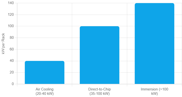
Cooling determines how dense that compute can be. Density selects the cooling method, not the other way around. Up to roughly 20 to 40 kW per rack, air cooling with containment works at a PUE of about 1.3 to 1.5.
Between roughly 35 and 100 kW, direct-to-chip liquid or rear-door heat exchangers become necessary.
Above 100 kW, immersion or two-phase liquid is the practical option, and PUE falls toward 1.02 to 1.2.
The reason is physical. Water has a volumetric heat capacity of roughly 4,180 kJ per cubic metre-kelvin. Air is about 1.2.
Fan power scales with the cube of airflow volume, so at high density the air-moving equipment consumes an unacceptable share of the power it was installed to support.
Network determines which workloads the facility can serve. AI clusters run two physically separate networks. A front-end network carries storage and management traffic.
A back-end network carries GPU-to-GPU traffic on InfiniBand or RoCEv2 in a non-blocking spine-leaf topology.
Route diversity and interconnect capacity decide whether a building can host distributed training or only inference and enterprise tenancy.
How a decision in one reshapes the others
Raising rack density raises power draw and cooling load at the same moment.
These are not sequential effects. They are the same decision expressed in two disciplines.
Choosing liquid cooling then changes the electrical design. In the Siemens and nVent 100 MW GB200 reference design, each pod uses four 415V, 3,000A switchboards feeding overhead busways.
Coolant distribution units receive four independent 30A feeds; standard network and support racks receive two.
That asymmetry exists for a reason. A rack can briefly survive primary power loss if coolant keeps flowing.
It cannot remain powered without coolant flow. Cooling therefore carries its own redundancy layer, separate from IT load redundancy.
Electrical topology then sets the shape of that layer. N+1 adds one spare unit, 2N provides two fully independent systems, and 2(N+1) combines two independent N+1 systems.
Cooling loops mirror the chosen topology so cooling does not become the weak link in a fault-tolerant design.
The network then feeds back into power. Back-end AI fabrics are rail-optimized, with the same NIC position on each node connecting to the same leaf switch.
That physical cabling requirement dictates where GPU racks can sit.
Distance then becomes a power cost. Direct attach copper draws zero watts but reaches only 1.5 to 3 metres.
A 1.6T optical module draws 25 to 30 watts, while a fully populated 32-port switch dissipates nearly 1,000 watts before compute.
At cluster scale, that adds megawatts to IT load, UPS sizing, cooling capacity, and interconnection demand.
So the floor plan is now drawn backward from the fabric. Leaf switches and rail-connected racks stay within copper reach to avoid optical power and cooling costs.
Cable pathways, chilled water piping, and busways then compete for the same space, requiring coordinated planning under ANSI/TIA-942.
What AI changed
GPU racks draw many times the power of traditional racks.
H100-class accelerators drew roughly 700 watts each. B200 and GB300-class parts draw more than 1,000 watts each.
That density forces liquid, and liquid reshapes the building.
Then the network intensity of distributed training raises interconnect capacity and interconnect power together.
The three systems arrive at the design table simultaneously rather than in order.
A worked example
NVIDIA’s GB200 NVL72 holds 18 compute trays, 36 Grace CPUs, 72 Blackwell GPUs, and 9 NVLink switch trays in a single cabinet.
It draws roughly 120 kW, with some configurations reaching 132 kW.
None of it works without all three systems designed together.
Standard AC power cords cannot deliver 120 kW to a cabinet, so central DC busbars and power shelves replace individual server power supplies, freeing space for GPUs.
Air cooling also falls short at this density, requiring cold plates and rear-frame manifolds to cool GPUs, CPUs, and NVLink switches directly with coolant at roughly 45°C.
The network decision closes it. Inside the rack, passive copper twinaxial cables form a blind-mate backplane delivering 57.6 terabits per second of full-duplex bandwidth per switch tray.
Copper eliminates thousands of transceivers and saves kilowatts per rack. Copper also attenuates quickly, which is why all 72 GPUs and 9 switches must sit inside one frame.
That packaging is only possible because the DC busbar freed the space and the liquid loop removed the heat.
Vertiv and NVIDIA describe the objective of their joint reference architecture as reducing stranded power by aligning AI clusters to data center capacity blocks.
In the Siemens design, the pod boundary is set jointly by electrical block size, a 1.63 MW liquid heat load per pod, and the NVLink domain size. No single discipline sets it.
What this means for each party
For developers. Co-design the three systems from the start.
Sequencing them invites the rework that moves schedules, because a cooling change late in design reopens electrical, structural, and layout work that was already approved.
For investors. A design that treats power, cooling, and network as separate work streams is a design that will change during construction.
Two assets with identical grid capacity can differ substantially in the compute density they can host, and that difference is set during design, not at interconnection.
For operators. The integration quality inherited at handover sets the efficiency, the density ceiling, and the failure modes for the life of the asset.
A hall commissioned correctly for 10 kW racks cannot take GPU tenancy without a cooling retrofit, and that retrofit brings a redundancy layer never included in the original electrical budget.
For policymakers. These choices drive grid load and water use together.
Open cooling towers consume roughly 2.0 to 4.0 litres per kWh of IT energy. Closed-loop direct liquid cooling consumes roughly 0.0 to 0.1.
Grid interconnection studies commonly take 12 to 24 months or longer, and in constrained markets the total delay runs to several years.
Key takeaway
You do not design a data center’s power, then its cooling, then its network. You design one integrated system, because the three are bound together, and the facilities that ignore that binding pay for it in construction.
The cost rarely appears as a single failure.
It appears as stranded capacity, as rework when a cooling change reopens approved electrical work, and as a density ceiling the operator inherits and cannot move.
None of that surface in a discipline-by-discipline review. Each review passes. The building still falls short.
Which of the three systems do you think design teams most often treat in isolation, and where does that isolation show up later?
Part 11 examines the contracts that set your timeline: Procurement Strategy — Equipment Vendors, EPC, and the Contracts That Set Your Timeline